Thanks for Visiting!
Have any questions or comments? Please feel free to contact us by reaching out through the form below. We look forward to hearing from you!
Your Complete Source for Infrared Inspections and Thermal Imaging

Thermography Inspection is the best tool to identify sources of energy loss.
Only one thing can reduce your total energy usage and lower utility bills. It’s the knowledge of knowing what the problem is! Winter or summer, knowing where the sources of energy loss are is the first step to reducing energy costs. Missing insulation and drafts are the main sources of discomfort; Infrared Thermography can identify the location of both of these sources.
When you need information, an Infrared Building Envelope Inspection is your roadmap to finding energy loss problems! Contact us at 845-641-5482 and we’ll show where you are missing insulation and where the drafts are coming from..
We leave this picture up year round not only because it’s an amazing shot of what an ice dam looks like, but because it reminds us that the energy loss which cause ice dams to form in winter are the same problems which increase summer cooling costs, poor insulation and air leaks.
Infrared Building Envelope inspections on commercial and residential structures find the exact locations of missing insulation and air infiltration. There is no other way to accomplish this as effectively and easily as an Infrared inspection.
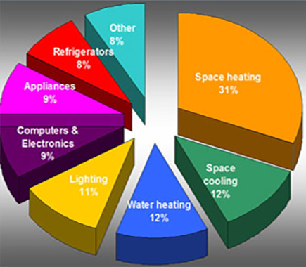
Unfortunately, a large portion of that is wasted! An Infrared Thermographic inspection of your home will find missing insulation in the walls and locate the source of drafts. This chart shows where we use energy in our homes. As you can see, heating, AC and hot water make up 55% of your energy usage. That leaves 45%, almost half, mostly in electricity! Source: 2007 Buildings Energy Data Book
An Infrared envelope inspection goes beyond the typical building inspection by adding the power of infrared Imaging technology, to give you the “big picture” of where building insulation is deficient. Infrared will locate areas of energy loss, which are increasing costs. Infrared Thermography is recognized as the fastest and most cost effective way to find energy loss. Infrared is a proven diagnostic technique recommended by the US Department of Energy for identifying areas of heat loss. The infrared images below show missing insulation in the walls and air leaks. Only infrared can effectively find these problems. An “energy audit” which doesn’t use infrared cannot find where insulation is displaced or missing. A “free” audit that doesn’t use infrared inspection cannot not find where the contractor may have missed placing insulation in walls. We are Certified level III Infrared Thermographers using high resolution infrared cameras and we find the problems other can’t.
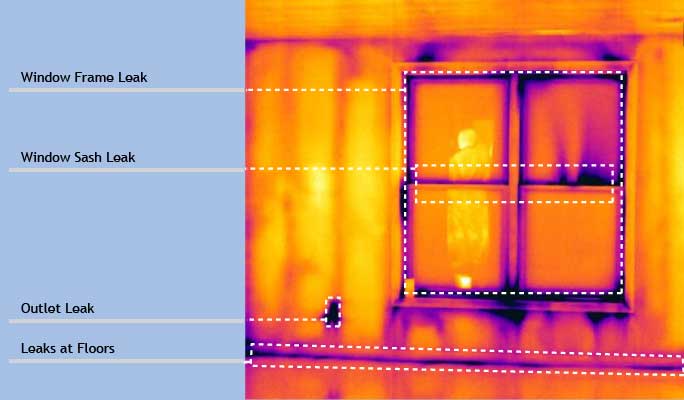
In this image of a typical wall and window, the dark purple shows the places where cold air leaks in. Each leak is a blast of cold air making you uncomfortable and costing money on your utility bill! Infrared Thermography found the leaks around the inside of the window frame, the window moldings and the right side window sash in the center. Also, the outlet box leaks and there is cold air on the floor coming from the exterior wall. Infrared imaging and a diagnostic blower door test is the fastest most effective way to detect air infiltration leaks. Thermpgraphic inspections find problems.
This room is cold because the ceiling is missing Insulation. Only an infrared inspection can find these problems instantly!
Purple area indicates missing insulation. The contractor installed the AC vents but removed the insulation! Infrared inspections pay for themselves with the energy you can save.
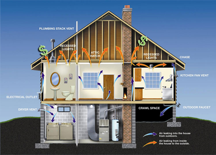
Drafts are caused by an air pressure imbalance. As warmed air rises to the upper levels of the building, it creates a positive pressure and leaks out of the gaps and cracks in the building’s envelope. At the same time, a negative pressure is created at the lower levels actively sucking in outside air to replace what leaked out at the top. In the Northeast, this replacement air is cold and dry in wintertime and hot and humid in summertime. We call the replacement air a “Draft”, and it wastes energy. This natural air circulation caused by the rising warmed air is called the “Stack Effect”. The taller the building and the stronger the temperature gradient from top to bottom the stronger the effect is. It’s costing you money right now and infrared can show you where the gaps in the building are!
In Floor Leak Detection of Radiant Floor Heating Systems and Steam Heating Systems:
Hot water pipes used in subsurface heating systems such as radiant floor systems or steam conduits contained within a concrete slab can cause major property damage and energy loss when leaks occur. These pipes are not readily visible on the floor’s surface, necessitating a costly and destructive effort to dig until the leak source is located. Failure to find a leak quickly can result in energy wasting boiler fill, damage to wooden structures, undermining of the concrete slab floor along with mold, insect and moisture problems. Infrared Imaging Services is experienced in finding sub surface leaks in radiant floor heating systems and steam supply and condensate return lines. We are experts at finding steam systems leaks in cement slabs and outdoors at large buildings and complexes. We specialize in helping building owners and their plumbing contractors to quickly locate leaks in steam systems and radiant floor heating systems, eliminating the need for the random destruction and costly digging to find the defect.
These infrared images show leaks in a radiant heating system and an underground steam pipe.
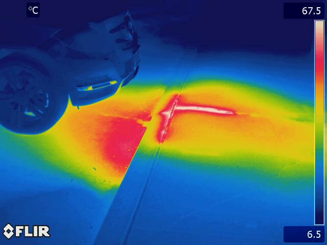
Thermal imaging precisely locates a break in an underground steam pipe in a parking lot.
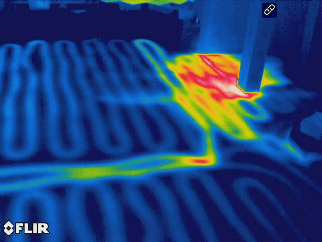
Thermogram detects a leak in a radiant heating system. The pipe layout is visible as is the flow of water under the concrete floor.
NEVER buy a new home or make payment on a new addition without doing an infrared inspection first as most contractor mistakes are buried in the walls. The image on the left is of a new addition just built and paid for. You can see the missing insulation along the front left wall. The entire wall should be dark blue. except for the studs, which would appear warmer. Yellow at the top and bottom is heat leaking! Whenever a contractor works on the structure of your home always insist for an infrared scan to ensure quality control. The cost of the scan is minimal compared to the overall cost of the project. New windows, which are not installed correctly, will not give the energy savings and comfort benefits described in the marketing materials and promised by the sales person. An Infrared scan and Blower door test is the only way to make sure you get what you paid for when buying replacement windows! With Infrared, it’s easy to see why the living room on the other side of this poorly installed replacement Bow window is cold!
In the images below, note the heat leaking from the window bottom. On the inside, blower door testing confirms air leakage from multiple places on the interior of this window, which are easily seen in the high-resolution images shown below.
Homeowner complains the room is cold and drafty.
Cold air (blue) can be seen leaking in from around the window frame creating drafts.
Cold drafts coming from door where the weather seal was defective.
In this image, we can see the bright hot spots showing exactly where there is a problem with the insulation behind the wall. The insulation behind the wall in the attic is displaced and is allowing the superheated attic air to make contact the rear surface of wall. The areas in yellow/white show the heated wall. As the wall heats up it radiates this heat into the room, causing the air conditioner to work harder and waste energy dollars.
Older recessed lights are bad because they leak air. Non sealed, not airtight recessed lights are big energy wasters because It’s like having a hole in your ceiling. The two infrared images below taken in summer during a diagnostic blower door test show how the warm attic (in yellow on the left and red in the below image) air is easily drawn into the home. In winter, your heat exits through these holes just as easily. Also, older lights are not rated to be in contact with insulation so usually there is a large space around the light, which is not insulated! The image to the left of a recessed light fixture was taken during a blower door test . It clearly shows streaks of hot attic air leaking into the air-conditioned living space. In winter, Its cold air escaping into the attic. How many leaks like these leaks do you have in your house wasting energy dollars? Let us show you where they all are.
On the right is an interesting image shown in visible light below. The outside temperature was cool at 55 degrees and sun was shining, making the attic warm. Look at where the wood wall meets the ceiling. During the blower door test you can see the cool air in blue being drawn in from the outside and at the same time the warm air from the attic, shown in red is drawn in from around the recessed light and near the top of the paneling. This house is in desperate need of air sealing! Infrared and Blower door testing is the best way to find complex insulation and leaky air problems.
This is a visible light image of a recessed light. The outside temperature was cool at 55 degrees and sun was shining, making the attic warm.
Look at where the wood wall meets the ceiling. During the blower door test you can see the cool air in blue being drawn in from the outside and at the same time the warm air from the attic, shown in red is drawn in from around the recessed light and near the top of the paneling.
Infrared and Blower door testing is the best way to find complex insulation and leaky air problems.
In this image, is a wall in the living room. Behind the upper part of the wall is an unheated attic space. Notice the dark blue square, indicating this part of the wall is colder than the rest. Note at the center bottom of the blue square is a small orange/yellow box; this is a sensor for the burglar alarm. The square patch of blue (and the other blue areas) is where the alarm installer did not replace the insulation behind the wall after he mounted the sensor and ran the wires. This home is loosing energy into the unheated attic.
Infrared makes it easy to see where cold air (in dark blue) is leaking in from under the window and from where the floor and wall meet. This room has air leaks along the entire length of this wall/floor making it very drafty. Also visible is the dark blue spot about 1/3 from the left side of the window just under the window sill. You can see where the insulation does not reach all the way to the bottom of the window creating a cold spot, leaking energy and allowing cold air into the home.
The center photo below shows a leaking air conditioner duct. The cold air (shown in purple) is escaping from the corner where the two ducts meet. The ducts were leaking costly air-conditioned air right into the hot attic. An examination of all the ductwork in this home showed similar leakage at every seam where two ducts were joined.
The third photo shows the cold air (blue) leaking from the air conditioner blower mounted in the attic. This was a significant air leak, the connection between the ductwork shown in silver/red on the right and the blower frame had a large gap which was not sealed. The dark blue patch is the cold air stream blowing out and up from the gap. This air was blowing so strong that it even made a cold spot on the attic roof causing condensation! The installer had forgotten to apply sealing tape and the homeowner’s energy dollars were paying to cool the attic!
The configuration of your AC/hot air heating system and where the duct leak is located will cause your home to have either a positive or a negative pressure. Positive pressure is usually the result of duct leaks located somewhere on the return side of the system. Instead of the blower sucking all of its return air from the home, it gets some portion of its air from the leak site(s), which are typically located in the unconditioned spaces such as the basement or attic. As these sites are usually outside of the homes pressure envelope, consider them to be a source of extra air. This additional air pressurizes the home and forces the air you paid to heat or cool out through all the cracks, vents and leaks in the buildings shell. Negative pressure is usually the result of duct leaks located somewhere on the supply side of the system. Instead of the blower pushing air back into the home, it pushes some portion of its air out through the leak site(s). As these sites are usually outside of the homes pressure envelope, consider them to be a source of lost air. As the system runs, the blower continues to pull in from the air return regardless of what is being lost. This creates a negative pressure inside the home while the air you paid to heat or cool is blown out usually into the attic or basement. Because of the negative pressure replacement air from outside gets forced in through all the cracks, vents and leaks in the building to replace what was lost. Both conditions are inefficient and cause unconditioned outside air, dust, moisture, pollen, etc. into the home and waste energy. In addition, a home under negative pressure can affect the proper venting of gas appliances such as your hot water heater or furnace/boiler. “With our high resolution Infrared cameras, we can quickly find these problems and many more sources or energy waste in your home or office!”
Infrared Imaging Services is a division of Jersey Infrared Consultants and a member in good standing of the United Infrared Network. As a member, we receive support for our customers from industry experts with decades of combined experience. We are certified for BlockwallScanIR™, EnergyScanIR™ RoofScanIR™. ElectricIR™, and DataCentIR™. Call or use the Contact us page to discuss your commercial thermal imaging needs. We provide infrared electrical inspections as requested by your insurance company. We are Level III thermographers certified by the Infraspection Institute.